The last post noted that the two most popular synthesizer filters are the 2-pole state variable, and the 4-pole “Moog style”. And we started with the state variable—simple, popular, and delivering multiple filter outputs (lowpass, bandpass…) simultaneously. Here, we’ll follow up with comments on the filter associated with Moog (and especially the Minimoog). In general, we’ll refer to this as a 4-pole synth filter.
While this filter is usually thought of as a lowpass filter, the other popular filter types can be derived easily. Many people first saw this in the Oberheim Xpander (and Matrix-12) synths of the ’80s, the idea came from Bernie Hutchins’ Electronotes in the ’70s. So don’t feel that you must go the direction of the state variable is you want multiple filter types, including 2-pole response.
Lowpass response is the overwhelming choice for typical synth use. Note that a 4-pole lowpass is not necessarily better then a 2-pole (as in the state variable)—they are just choices. You might want a 4-pole for the darker Minimoog bass sounds, and a 2-pole for the brassy OB8-style sounds.
Basic construction
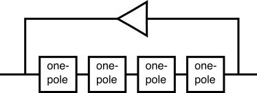
The 4-pole is implemented by a string of four one-pole lowpass filter in series. We need corner peaking and resonance control for a synth filter, and we get that by feeding back the output to the input. While trivial in the analog domain, this feedback is the tricky part in the digital recreations. The reason is that it’s not a continuous system, and the obvious way to handle it is to put a delay in that part, so the output of the current sample period is available as input for the next. But this creates some bad side effects, particularly for tuning. In the past, people dealt with this by accounting for those errors.

Approaching analog
But it’s not just tuning errors—if it were, that would be simple to fix. The Minimoog popularity, in part, is that it is designed to easily overdrive the filter, to get a “fat” tone. This is another thing that is simple in the analog domain, but doing the same in the digital domain produces noticeably digital artifacts. And if your goal is to make something that sound analog, this is a source of spectacular “fail”.
So instead of this simple delay approach in the 4-pole feedback path, modern ideas use more complex techniques to avoid the large-scale errors in an effort to get closer to how the analog counterpart works. And part of the effort is in dealing with an overdriven feedback path. The result reduced digital artifacts, makes the filter’s behavior more closely resemble its analog counterpart when overdriven, and also gives a smoother, more predictable and more musical sound at high resonance.
Note that these techniques are often called “zero feedback delay” (ZDF) filters. That is meant to highlight the fact a trivial delay is not used. I’m not a huge fan of that, since it’s not meaningful to someone who doesn’t know of the delay it refers to, and of course there are always sources of internal delay in an such filter design. But I mention ZDF so that if you’ve heard it before, be assured that we are talking about those sort of techniques here.
Serious reading
A great resource for this topic is Vadim Zavalishin’s The Art of VA Filter Design (“VA” for “Virtual Analog”).


I must admit, I’m pretty stoked to hear your explanation of this Nigel – I’ve heard of ZDF filters but don’t really understand them as yet. Your articles have helped me tremendously in the past, so I look forward to reading this series!
Great post Nigel.
I’ve had a go at implementing a view VA filters based of The Art of VA Filter Design and managed to construct a moog ladder style with success.
Will Pirkle also has some really good implementations on his website and in his synth book.
I’d thoroughly recommend the bus Musimathics Volume 2 for anyone wanting to understand this stuff as it helped me out with the mathematics needed to understand Vadmin’s paper.
The following site is also great to help understand how integration and differentiation apply to analogue filters – http://www.learnabout-electronics.org/ac_theory/filters.php.
This also really helped me out understand the mathematics behind that paper.
Would love to see an Ear Level code interpretation of all this stuff one day!
Josh
Thanks for the references, Josh. I also came across Will Pirkle’s applications notes—I figured I’d get wait till I have a chance to get and read at least one of his books before putting a recommendation here, but his work also looks like a terrific resource.
Hi Nigel
You might want to dig up two AES convention papers I published a couple of years ago: “Resolving delay-free loops in recursive filters using the modified Härmä method” and “Novel hybrid virtual analog filters based on the Sallen-Key architecture”
My Synth book is chock full of virtual analog filters as well, and goes into depth regarding the modified Härmä method (and Zavalishin’s algebraic method).
Also, FYI — I use your EG implementation in that Synth Book, and I also credit you in the text, and your webpage is in the Bibliography. The derivation of time constants I chose is my own work; the analog-modeling EG uses the CEM3310 IC as a basis, while the “digital” version uses the MMA DLS Level 2 Spec’s “linear in dB” EG for decay and release.
All the best,
Will Pirkle
Hi Will—thanks for stopping by!
I actually own your synth book, haven’t had time to read it, sorry to say. Bought the google books version to try that format. I regret not having a physical book, probably would have been able to read it by now, here and there.
So, I didn’t now you referenced me in the book till now—thanks! I’ll definitely dig into the filter stuff “soon” (finish of current project).
Regards,
Nigel