
WaveUtils needed only a minor change for compatibility with the WaveTableOsc update—addWaveTable changes to AddWaveTable. But I added something new while I was at it.
The original wave table articles advocated minimizing the number of tables necessary—one per octave—by allowing a reasonable amount of aliasing. Aliasing that is not only difficult to hear, but is normally be removed in typically synthesizer applications by the synth’s lowpass filter.
But that is simply a choice of the individual wave tables and how much of the spectrum we’re willing to let each cover. We could use more wave tables and allow no aliasing at all.
In addition to the fillTables function, which builds active wave tables. I’ve added fillTables2, which accepts a minimum top frequency, and a maximum top frequency. For instance, we might want to support a minimum of 18 kHz, using a value of 18000 divided by the sample rate, so that harmonics are supported to at least that frequency. If we use 0.5 for the maximum, then no aliasing is allowed. Higher values allow aliasing. For instance, a value of 0.6 allows a top frequency of 0.6 times the sample rate, or 26460 Hz at 44.1 kHz sampling. That’s 4410 above half the sample rate, so aliasing can extend down to 17640 Hz (22050 – 44100). Another way to look at it is to subtract the value from 1 and multiply by the sample rate to get the alias limit, (1 – 0.6) * 44100 = 17640.
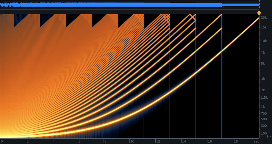
Here are some examples. First, the original octave tables. To understand the spectrograms, time is left to right—a 20 second sweep from 20 Hz to 20 kHz of a sawtooth. You can see the aliasing as harmonic frequencies bend down at the top, although the algorithm minimizes the aliasing with advantageous choices of switching frequencies at the highest sweep frequencies, where there is the least masking. This uses ten wave tables to sweep the ten octaves of audio from 20 Hz to 20 kHz.
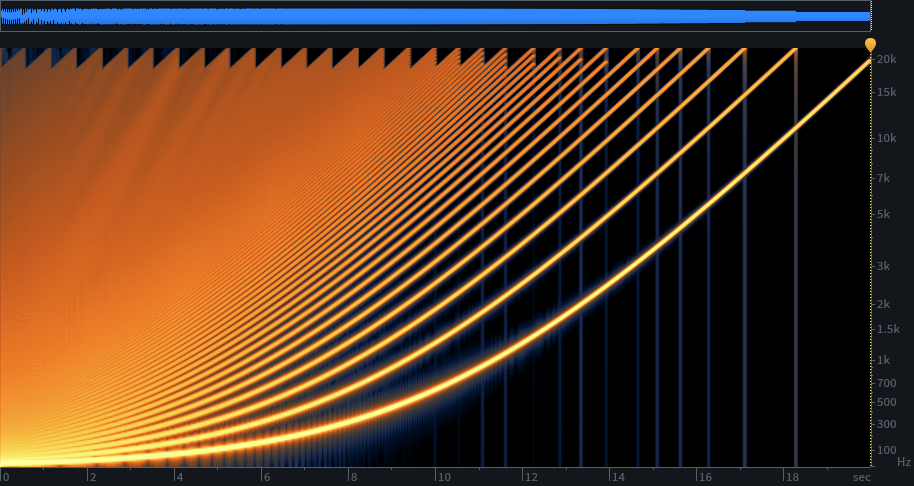
I think the aliasing is masked pretty well. But if the idea of aliasing bothers you, and you want at least 18 kHz coverage, 34 wave tables will get you this, at 44.1 kHz sample rate:
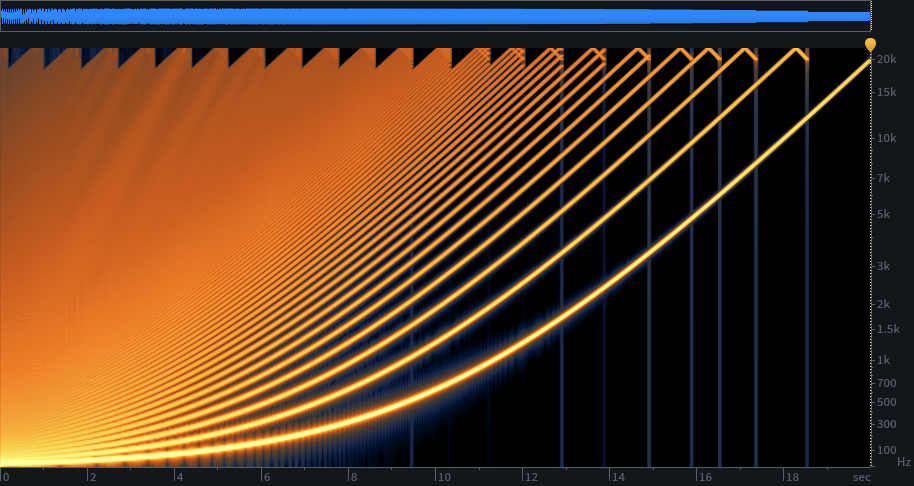
Now for an asymmetrical example. If you want 18 kHz, but are willing to accept aliasing above 20 kHz, 24 wave tables will do it:
The tables look pretty, I bet they sound pretty too 🙂
Don’t miss that you can play them too—the player underneath the screenshot happens to look almost like part of the screenshot…
Ps great to see regular postings, i always look forward to them!
Hi – thanks for all the great sharing with the community. I do have a question:
I don’t understand your design for determining the top frequency you will allow (with aliasing). Here is what you say in the code:
// calculate topFreq for the initial wavetable
// maximum non-aliasing playback rate is 1 / (2 * maxHarmonic), but we allow aliasing up to the
// point where the aliased harmonic would meet the next octave table, which is an additional 1/3
double topFreq = 2.0 / 3.0 / maxHarmonic;
Can you explain in more detail how the additional 1/3 meets the next octave table?
Thank you!
Yes, good question—something that’s definitely takes some thinking to figure out for the first time.
Obviously, it’s all about the harmonics—a sine oscillator only needs one table for full range and no aliasing. We need to support harmonics through the audio range, or close enough we can’t tell. We can use fewer tables if we allow aliasing. We start with a goal of one table per octave, and see if that’s adequate.
For an octave, the highest frequency is obviously twice the lowest. And we’re really concerned with the lowest and highest frequency of the highest harmonic for the particular waveform being generated. That’s why maxHamonic is in the calculation.
For 44.1 kHz minimum sample rate support, we need the lowest support frequency to be as high as we can get, but we need to contain aliasing too. If the low end of the octave table is 1/3 the sample rate, an octave up is 2/3—which aliases back down to 1/3. So, our first 1/3 of the sample rate (2/3 of the available audio band), or 0-14.7 kHz, is available and alias-free at 44.1 kHz. That’s just barely good enough, but of course at higher rates it’s better, or we can use tables that cover a smaller range.
My table allocation method for octaves works out well on the high end, where higher harmonics are few and louder but there is less aliasing (see the spectrogram—the last few tables have less aliasing despite covering an octave), and the increased aliasing at the low end is masked by denser harmonics and quieter aliasing, so 14.7 kHz ends up being better than it would seem. And a synth usually has a lowpass filter in the chain, rarely fully open unless the oscillators have limited harmonic content.
With the new code here, I allow separate setting of the low and high frequency.
Hi – I ran into another curiosity that I’d like to ask about.
I have an implementation based off of this code and I’ve been testing it with pre-rendered single cycle simple waveforms – sine, saw, square, pulse, triangle, etc). I noticed that for the pulse wave only, when I run it through the fft/ifft, I get a dc offset. This doesn’t happen for any of my other waveforms I test with. I’ve even just done a fft/ifft with no spectral processing and still get the dc offset.
Curiously , the dc offset is proportional to the pulse width – for a 1/4 pulse width, the top of the pulse is at .5. For 1/8 pulse width, the top is at .25.
This seems like a property of pulse waves and not a coding error – but I can’t find anything in my endless googling or reference books. Is there something special going on with a pulse wave that makes it transform via the fft/ifft process?
Thanks!
I investigated this a bit further and surprisingly it turns out that I only get the pulse width dc offset when I set the first bin to 0 after the fft. My understanding was that this was standard operating procedure to ‘remove’ the dc offset when generating wavetables. So there is something I don’t quite understand about why this is the case – is there any thoughts you have as to why I need to remove the zeroing of the first bin to keep my pulse wave consistent? Thanks!
Yes…here’s something you can try in a graphing calculator: y = cos(0x) + cos(1x) + cos(2x)…that is, a summation of cos(nx) with n=0..max, infinitely narrow for max = infinity. It’s a pulse train. Note that cos(0) is just a DC offset, of the same amplitude as all the other components. If you get rid of the DC component, then the waveform will ride up or down depending on the pulse width—basically balanced with the duration above and below zero.
Thank you for this explanation – it definitely explains why I see the dc offset.
Tying this back to wavetable oscillator design – rectangular waves seem like an exception to the practice of setting bin 0 to 0 (to eliminate dc offset). But I’ve tested some other wavetable synths (like Serum, Pigments, and Dune 3) and they all load a rectangular wave fine without showing any dc offset. Is there a general solution for a wavetable oscillator that handles multiple (even user input) wavetypes so that it doesn’t have to treat a rectangular wave special?
Things that occur to me:
1 – continue to set bin 0 to 0 and after converting back to the time domain, check the min/max of the wave and shift to be centered around 0.
2 – Handle this with normalizing the wave. Some iffts normalize to the sample size for you (like Juce’s dsp::FFT) so this would be an extra step after that.
Both of these seem clunky – is there a better solution?
I’m not sure you understand DC offset correctly—are you considering it the mid-point? Two ways to look at it, first frequency domain: If you set the DC component to zero, all of the other sinusoids are centered symmetrical about the zero line. It doesn’t matter that if you translate that to the time domain, the wave might not be centered. Second, time domain: If a single cycle wave has no DC offset, the average of all the samples is the DC offset. So, just summing all the samples yields zero if there is no DC offset. In a synth, some waves have DC offset, usually for low frequency use. For a rectangle wave, you don’t want an LFO’s high low extremes to shift around as you change the duty cycle (pulse width), for instance.
In fillTables() I don’t understand this line of code:
double topFreq = 2.0 / 3.0 / maxHarmonic;
maxHarmonic is the highest bin-index into the FFT result, where you found some relevant energy. But this line of code does not reflect the total number of bins. If the FFT result has 128 bins, maxHarmonic means a different frequency than if the FFT result has 1024 bins. I think, somehow ((float)maxHarmonic / NumBins) must be incorporated. Can you shed some lighht into this?
topFreq is the normalized frequency that a given table is designed for, minimizing aliasing, normalized to the sample rate. Tables designed for lower frequencies can have more harmonics, so we want to play back from the lowest table that we can. We pick the first table in the list with a topFreq at or above the oscillator frequency.
While fillTables2 can design oscillator tables with any aliasing allowance, including zero aliasing, fillTables builds one table per octave, allowing aliasing at the highest frequencies. Basically, fillTables is designed to build the cheapest oscillator of acceptable quality. If we allow topFreq to be 2/3 of the sample rate, that allows aliasing down to 1/3. That means the highest table (which has a maxHarmonic of 1, a sine wave) will have a topFreq of 32k for 48k sample rate, which would alias down to 16k. The second highest table would be half that topFreq, and so on—that’s why the topFreq value gets divided by maxHarmonic.
I think the most “accurate” and clean results is the second example: “8 kHz coverage, 34 wave tables and no alias”.
The only difference I can think of is to pick the right wavetable index across 34 tables instead of 24. Is this really a big deal? Or permit “alias” to the high end introduce some sort of sonically advantage?
In few words: you just “permit alias” only for decrease the numbers of wave tables?
Yes, “permit alias” decreases the number of tables. As long as the aliasing doesn’t isn’t low enough to hear, if doesn’t matter. Also, the higher the sample rate used, the the fewer tables needed, even without aliasing.
Not sure about this (i.e. more alias allowed, fewer table).
In any case you did while()…maxHarmonics >> 1
So the number of table is the same.
Starting from 736 for example: 736, 368, 184… 1 = 10 tables.
The only things that change is the topFreq threshold, that’s why I don’t get the point of allow/not allow alias, if sonically nothing change 🙂 Hope you get my dubt?
“The only things that change is the topFreq threshold, that’s why I don’t get the point of allow/not allow alias”—Well, that is the point. Allowing aliasing is just a design constraint, as is the top frequency. For instance, if you choose to allow aliasing, the total potential amount you are letting the frequency shift upwards doubles (the span from topFreq to half the sample rate, plus the same distance back down to topFreq if you allow aliasing), which can let you use fewer tables. For some people, the thought of aliasing bothers them, then can choose to not allow it.
I used an open source wavetable synth Octane (https://github.com/hsetlik/Octane). Finally found its core algorithm was based on your code. And now I’m using your algorithm in my own project. It has a good sound quality. Thanks you!